
|
Isuzu Trooper Owners Club UK
Isuzu Trooper, Rodeo, Bighorn, Mu & VehiCROSS Owners Club
|
| View previous topic :: View next topic |
| Author |
Message |
C.B.
***

Joined: 08 Mar 2008
Posts: 144
Location: Central Scotland
|
 Posted: Sat Dec 13, 2014 3:24 Post subject: Adding DRLs and using redundant rear body tail light unit Posted: Sat Dec 13, 2014 3:24 Post subject: Adding DRLs and using redundant rear body tail light unit |
 |
|
During some recent modifications to my old Trooper I added front and rear DRLs.
The front units have a set of white LEDs for the daylight running bit and a set of amber LEDs for indicator mode. These were bought as bolt on units and fitted perfectly above the fog lamps without any issues. (There was a slight problem with making the indicator mode work properly but a couple of series diodes in the units white light feed supply sorts that out by reducing the voltage enough to make the unit switch over to amber reliably).
The rear lights were installed in the unused chamber of the upper body combination light and I used 2 x 5mm white LEDs in each unit for that.
First job after looking over the manual and probing about in the wiring a bit was to add a control relay and the wiring I needed to connect everything up (after disconnecting the battery).
Heres the schematic diagram for the mods:-
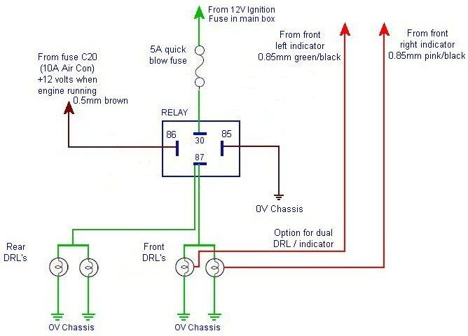
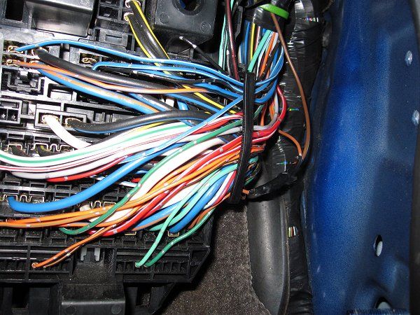
To get the control wire for the relay I spliced into the 0.5mm brown wire coming from fuse C20 in the cabin footwell fuse box, this circuit has 12v only when the engine in running. (C19 would have done as an alternative but it has a 3.0mm wire and slightly more awkward to splice neatly). The splice was done by carefully cutting through the insulation with a scalpel round the circumference of the wire in two positions about 8mm apart, then slitting between the two cuts and peeling the insulation off. Then I tinned the exposed copper wire with solder and soldered the end of a new pre-tinned wire onto the prepared joint.
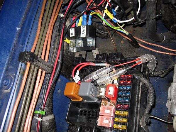
Once that was done I taped up over the joint starting below and ending above to ensure a good spiral wrap of insulation. The wire was then fed though to the engine bay, crimped and connected to the control relay (12v 30A) at pin 86. The supply line for the relay power (30) was taken from a freshly added 5 Amp fuse added to the main fuse box and the relay coil was earthed (85) with ring terminal bolted just next to the main fuse box.
Front wires were added between the relay NO contact (87) and the LED units +ve wires, a local earth to the LED units ve wires, and 2 wires from the front indicator units were spliced (by solder jointing) at the back of the unit and connected to the LED units optional indicator feed wires.
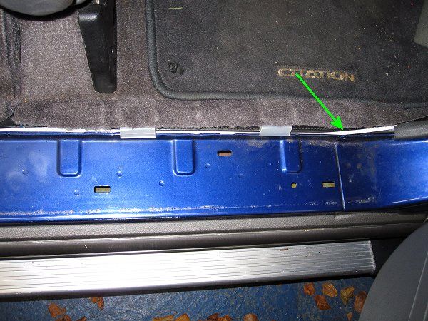
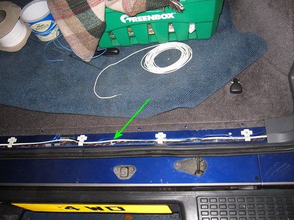
The rear wires were run from the engine bay back through the grommet, along the side of the bottom door seal, behind the o/s rear trim and then up to the rear o/s light cluster using 0.5mm flat twin mains cable. Another twin cable was taken back out, under the side trim, along the underside of the back door trim and up into the n/s light cluster.
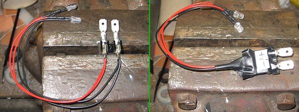
For the back lights I used 2 x high intensity 5mm white LEDs in each unit (these were pre-wired with resistors so they could be connected to 12v). Using a couple of terminal strips I soldered on the LED wires and two crimp blades (marking which was + and for the LEDs) so I could connect using crimp receptacles and still have the units easily removable.
I took the light units off the car and carefully drilled 2 holes into the plastic of the blanking area at the back of the top unused bay, then inserted the LEDs (tight fit) up to the shoulder and put a spot of fast drying plastic glue round them (to ensure they didnt eventually vibrate out).
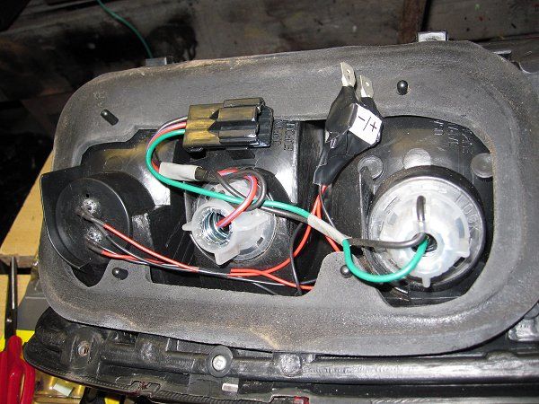
Last job was to crimp up the 2 feed wires with the link wires on the o/s and the two wires on the n/s, connect them up then bolt everything back into place, connect up the battery and check the result!
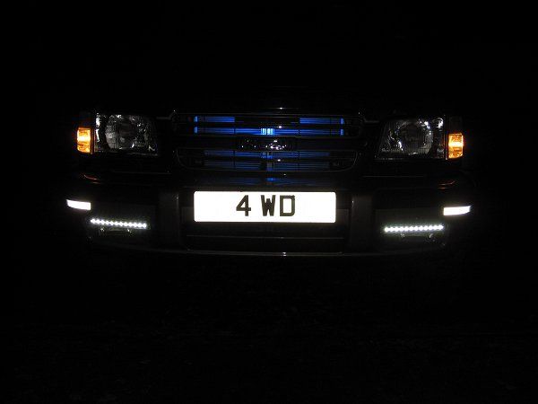
All done!    Heres the front (err... the bluish backlight for the chrome look radiator is another story) Heres the front (err... the bluish backlight for the chrome look radiator is another story) 
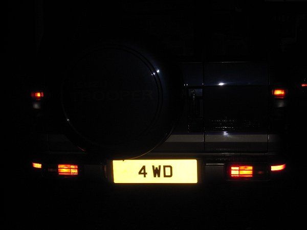
And the back
This took ages to do but most of it was investigation, planning and collecting the bits, hopefully this will help anyone else wanting to do something similar.
_________________
'00 3.5i V6 SWB Trooper (18 MPG  ) )
'02 SAAB 95T Aero (F.A.F.  ) )
'19 1.5D Nissan Van (Mr. NV  ) ) |
|
| Back to top |
|
 |
Google
Sponsor

|
| Posted: Sat Dec 13, 2014 3:24 Post subject: Google Ads keep this community free to join! |
|
|
|
|
| Back to top |
|
|
RolySC
Newbie
Joined: 01 Dec 2014
Posts: 6
Location: Ashford, Kent
|
| Posted: Wed Dec 24, 2014 8:59 Post subject: DRLs |
|
|
| Nice job! Looks very effective - if I have a week or two to spare I may have a go at this myself! |
|
| Back to top |
|
|
ggiinnggeerr10
*
Joined: 10 May 2015
Posts: 31
Location: middlesbrough
|
| Posted: Wed May 20, 2015 23:51 Post subject: |
|
|
| what lights have you got behined the grill |
|
| Back to top |
|
|
C.B.
***
Joined: 08 Mar 2008
Posts: 144
Location: Central Scotland
|
| Posted: Thu May 21, 2015 1:12 Post subject: |
|
|
I used one single sealed 17cm 12 volt 6 watt COB high intensity LED unit (ice blue).
Its stuck onto the inside of the front grille pointing back towards the radiator so that there's no direct light shining forward from the unit.
To make this unit work reliably (without overheating and burning out in a short space of time) it should be run off a regulated 12 volt supply, not straight off the battery. 
_________________
'00 3.5i V6 SWB Trooper (18 MPG )
'02 SAAB 95T Aero (F.A.F. )
'19 1.5D Nissan Van (Mr. NV ) |
|
| Back to top |
|
|
naksh31
Newbie
Joined: 25 Jun 2019
Posts: 1
Location: Pune
|
| Posted: Mon Aug 12, 2019 11:54 Post subject: |
|
|
| Excellent thread..!!! |
|
| Back to top |
|
|
|
|
|
You cannot post new topics in this forum
You cannot reply to topics in this forum
You cannot edit your posts in this forum
You cannot delete your posts in this forum
You cannot vote in polls in this forum
|
|

