
|
Isuzu Trooper Owners Club UK
Isuzu Trooper, Rodeo, Bighorn, Mu & VehiCROSS Owners Club
|
| View previous topic :: View next topic |
| Author |
Message |
albion
**
Joined: 20 Feb 2005
Posts: 64
Location: East Yorkshire, England
|
 Posted: Sat Feb 21, 2009 0:02 Post subject: Posted: Sat Feb 21, 2009 0:02 Post subject: |
 |
|
| Gribble wrote: |
If you can get the British trooper manual on line from the club somewhere page 7352 shows the wiring for yours.
Now I will assume that you have done the basics like fuses as there are 3 - C9 , C14 ,C16 all part of it.
Is the 'check engine 'light working still ?
Tech II will read the fault codes for this also the manual is showing KW2000 which is a common obd scanner protocol as its not a 3.0 a normal scanner may read it too.
Plug is just under the gearchange cover across from the clutch pedal |
Can you tell me where to find the manual? Trawled the site but no luck so far...
Thanks!
Albion |
|
| Back to top |
|
 |
Google
Sponsor

|
| Posted: Sat Feb 21, 2009 0:02 Post subject: Google Ads keep this community free to join! |
|
|
|
|
| Back to top |
|
|
Grandad
*******
Joined: 22 Sep 2005
Posts: 1902
Location: NORFOLK
|
| Posted: Sat Feb 21, 2009 0:05 Post subject: |
|
|
the wiring diagram
 |
|
| Back to top |
|
|
albion
**
Joined: 20 Feb 2005
Posts: 64
Location: East Yorkshire, England
|
| Posted: Sat Feb 21, 2009 0:29 Post subject: |
|
|
Thanks, Granddad! Greatly appreciated - will pass this to my brother Phil - he does the sparky stuff!
Albion |
|
| Back to top |
|
|
redhop
Newbie
Joined: 14 Feb 2009
Posts: 5
Location: gloster
|
| Posted: Sat Feb 21, 2009 10:27 Post subject: |
|
|
The thread has given me some ideas and now that the weekend is here I can start looking for solutions as I've only been able to read of your progress so far. One thing that has come to mind is that a ignition powered cable scotchlocked to the right cable via a in line fuse could act as a bypass to use in an emergancy if the power to the solenoid is intermitant. The only thing is to work out which wire to connect to at the fuel pump end. leaving out the fuse would act like a switch, replaced when/if needed. I'll report back any discoveries or progress.  |
|
| Back to top |
|
|
redhop
Newbie
Joined: 14 Feb 2009
Posts: 5
Location: gloster
|
| Posted: Sun Feb 22, 2009 9:28 Post subject: |
|
|
Have had mixed results so far with the fuel pump wiring. Having disconnected the plug and then refitted it the engine fired  but the next time it was tried it ran and stopped but the next time it was tried it ran and stopped  turned the key and fired and stopped but ran for about half the time it ran before which was only a second or so. I reckon that there was some fuel left the first time and then not much for the second time it briefly fired up. I again removed the plug and the same result turned the key and fired and stopped but ran for about half the time it ran before which was only a second or so. I reckon that there was some fuel left the first time and then not much for the second time it briefly fired up. I again removed the plug and the same result  So I have an engine that will run only if the plug is removed first and refitted and then its back to a non runner although a starter. As I want a car that can be used without pulling plugs off and on each time I start it I have left it for now and await any ideas So I have an engine that will run only if the plug is removed first and refitted and then its back to a non runner although a starter. As I want a car that can be used without pulling plugs off and on each time I start it I have left it for now and await any ideas  My only thought is to try and get at the plug and socket and see if I can effect a better wiring connection, though it is not an easy place to get at and may make things worse My only thought is to try and get at the plug and socket and see if I can effect a better wiring connection, though it is not an easy place to get at and may make things worse  |
|
| Back to top |
|
|
albion
**
Joined: 20 Feb 2005
Posts: 64
Location: East Yorkshire, England
|
| Posted: Sun Feb 22, 2009 9:52 Post subject: |
|
|
Hmmm - that sounds almost like it is re-setting something. If you unplug the pump, then re-connect it and start the engine, how long will it run for? Mine will start, rev to about 3000 rpm, then cuts off just as though you have turned the key off. Two or three attempts later it will do the same again. Going to check some more fuses today (although I can't quite believe it will be that simple) - so more later!
Earlier in the thread it was mentioned that fuses C9, C14 and C16 are the relevant ones. I've located two on the wiring diagram, but only one on the vehicle so far...mid you it took me ten minutes to remember where the cab fuse box is located - LOL!!
Albion |
|
| Back to top |
|
|
Gribble
*******
Joined: 11 Oct 2007
Posts: 8448
Location: Holset H221W
|
| Posted: Sun Feb 22, 2009 20:02 Post subject: |
|
|
Have had a thought on this one - if you can get the test plug out (no tools required ) and do this lot ;
Reading Flash Diagnostic Trouble Codes
The provision for communicating with the Engine Control ---------- Or the immobilizer since its got a diag link into it .
Module (ECM) is the Data Link Connector (DLC). The
DLC is located in the front console box. It is used in the
assembly plant to receive information in checking that the
engine is operating properly before it leaves the plant.
The diagnostic trouble code(s) (DTCs) stored in the
ECMs memory can be read either through a hand-held
diagnostic scanner plugged into the DLC or by counting
the number of flashes of the Check Engine Malfunction
Indicator Lamp (MIL) when the diagnostic test terminal of
the DLC is grounded. The DLC terminal 6 (diagnostic ---------------- Here use pin 7
request) is pulled Low (grounded) by jumpering to DLC
terminal 4, which is a ground wire.
This will signal the ECM that you want to flash DTC(s), if
any are present. Once terminals 4 and 6"to the ON
position, with the engine not running.
The Check EngineMIL will indicate a DTC three times if
a DTC is present. If more than one DTC has been storedin the ECMs memory, the DTC(s) will be output from the
lowest to the highest, with each DTC being displayed
three times.
The DTC display will continue as long as the DLC is
shorted.
I think if you can do this and post what codes are coming up it will save you time and money  The plug is tapered as you look at towards the pins and pin 1 is at the right hand side bottom row and pin 16 the top left side top row. 16 will show 12v+ with the key on . The plug is tapered as you look at towards the pins and pin 1 is at the right hand side bottom row and pin 16 the top left side top row. 16 will show 12v+ with the key on .
The code will be in a series of flashes like 4 blinks - pause 5 blinks and if Grandad is online he can look in the book and tell you what they are thus the problem can be sorted !
Would suggest that if an expensive component is identified as faulty then you could take your I/pump to a good Bosch injection place and ask for a standard stop solenoid to be put on and bypass the relay from the ICU to the starter thus getting you going less the immobilizer.
Other way is to have a tech II put on and have the immobiliser function disabled but you would need the 4 digit security code from an Isuzu dealer to do it.
Tech II is the hand held scanner that works on all Isuzu Troopers to diagnose and read codes and reset electronic componets. Usually with the dealer too ! |
|
| Back to top |
|
|
albion
**
Joined: 20 Feb 2005
Posts: 64
Location: East Yorkshire, England
|
| Posted: Sun Feb 22, 2009 23:54 Post subject: |
|
|
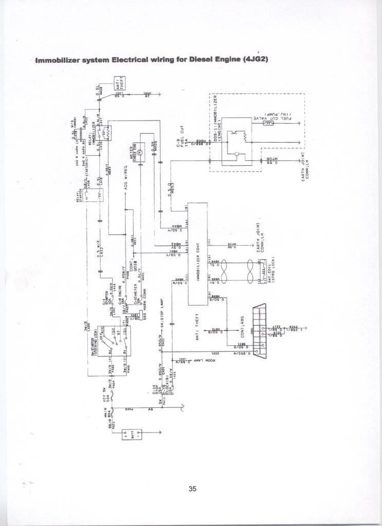
Thanks Gribble, this sounds like a way forward, I can do this Tuesday as I'm otherwise engaged Monday. One thing you and Grandad might have a ponder on meanwhile is the wiring diagram he sent me, which if you look carefully at the injector pump diagram (enclosed inside the broken line box at top right of the diagram, or bottom right if you are holding the A4 sheet landscape) doesn't make any sense at all!
We see the fuse C9 (fuel cut 15a) connecting to the immobilizer engine unit. One arm of this T connection goes to the collector connection of an NPN transistor, the emitter of which is grounded via a resistor, but nothing is connected to the base connection? This transistor is in switching mode and would switch on when the base potential was higher than the emitter, and it makes sense that this transistor would be biased (switched on) by the connection from the immobiliser control, thus putting the feed from the C9 fuse to the fuel cut valve, via the transistor. BUT, The wire from the immobilizer control does not connect to the base of the transistor, it connects instead to a little "box like" symbol (not an S.I. symbol that I recognise, or can find anywhere) between the C9 connection and "earth joint connection LH" Meanwhile the fuel cut valve apparently connects to nothing. I don't know whether the scanning of the page has not worked properly, or the wiring diagram is simply incomplete or wrong (it wouldn't be the first time!), but if I have to take the unit off the injector pump I will check it out, draw a circuit diagram of what I find, and post it back to the group.
Phil |
|
| Back to top |
|
|
Gribble
*******
Joined: 11 Oct 2007
Posts: 8448
Location: Holset H221W
|
| Posted: Mon Feb 23, 2009 0:38 Post subject: |
|
|
And there was me thinking I was putting too much info in the post !
You have a better idear than me of electronic notation but that drawing is just an outline since anybody can get it and if they are like you  would soon work out how to get round it so the minimum information is put in to prevent theft .. No doubt the dealers have some more info. would soon work out how to get round it so the minimum information is put in to prevent theft .. No doubt the dealers have some more info.
I do know that the black plastic bit is fail safe i.e if you try to get it off it breaks and its diesel pump shop time .
The signal into the unit from the ICU is encrypted at a low frequency and is Class II Serial Data so thats why the drawing looks wrong cos not all the components are shown .
If you have seen or done work on serial bus or can bus control systems you might be surprised to see it on a car of this age but thats what OBD1/11 is based on.
The problem from here on in is that I do not have any more info to post as to wires and readings ,possibly somebody else on the club may ?
My own thoughts are that if the aerial loop makes no difference the aerial is duff , it may have continuity but no broadcast over the key transponder so it would start and run whilst the starter was turning - has to or no start ?
The flash codes will read this . |
|
| Back to top |
|
|
albion
**
Joined: 20 Feb 2005
Posts: 64
Location: East Yorkshire, England
|
| Posted: Mon Feb 23, 2009 10:31 Post subject: |
|
|
Thanks for that info, I suppose it makes sense to prevent theft, but I do wonder if they are preventing repair by anyone who cant stump up £3500+ for the scanner, IE its a dealer only job, and it costs an arm and several legs, although the dealer will have it in the shop less than an hour. Don't worry, i'm just a bit miffed because we lost another vehicle over the weekend, our trusty (?) Berlingo threw its alternator belt into the cam belt with predictable valve bending results. apparently a common failing. The man who designed engines that self destruct when a rubber belt snaps should be roasted slowly over hot coals untill the flesh flakes from his bones  Well i will not try to remove the injector pump cover, but I will be using your method to test for fault codes, and also maybe removing C9 fuse and putting an ammeter in its place to read the current which will tell me when the solenoid is operational, and more importantly, when it isn't! Has anyone in the club any experience of this scanner, which claims to do the job required? Well i will not try to remove the injector pump cover, but I will be using your method to test for fault codes, and also maybe removing C9 fuse and putting an ammeter in its place to read the current which will tell me when the solenoid is operational, and more importantly, when it isn't! Has anyone in the club any experience of this scanner, which claims to do the job required?
http://cgi.eebuygum.co.uk/BEST-Universal-code-reader-scanner-FOR-1982-2009_W0QQitemZ220356106778QQcmdZViewItemQQptZUK_Diagnostic_Tools_Equipment?hash=item220356106778&_trksid=p3286.c0.m14&_trkparms=72%3A1683|66%3A2|65%3A12|39%3A1|240%3A1318
Phil |
|
| Back to top |
|
|
Gribble
*******
Joined: 11 Oct 2007
Posts: 8448
Location: Holset H221W
|
| Posted: Mon Feb 23, 2009 12:42 Post subject: |
|
|
Ah now I went the same route as you on a 3.0 but soon found its Tech II only. I dont know about the 3.1 with the later immobilizer as I have not tried that type of code reader on one 
Some of the motor trade members may well post a reply for this.
Thing is that scanner in the link will only read the code (if any) if its one in its memory so you would be no further forward than the flash codes but out of pocket
Also another simple test that just came to mind - with jump leads or similar make a fresh earth from the engine to B - and body to B- but dont use the same body earth as the loom . |
|
| Back to top |
|
|
Grandad
*******
Joined: 22 Sep 2005
Posts: 1902
Location: NORFOLK
|
| Posted: Mon Feb 23, 2009 13:09 Post subject: |
|
|
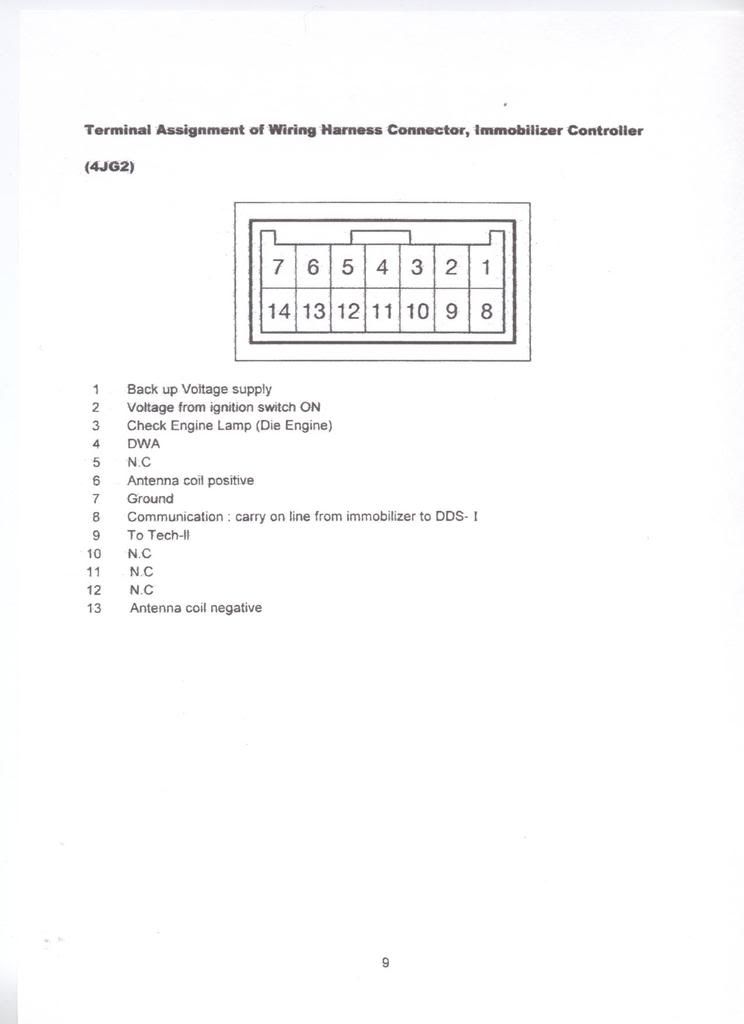
I can find no reference to the little box symbol in the info i have the wire leading to it is no8
 |
|
| Back to top |
|
|
albion
**
Joined: 20 Feb 2005
Posts: 64
Location: East Yorkshire, England
|
| Posted: Tue Feb 24, 2009 13:56 Post subject: |
|
|
| right, tried the shorting trick to get the fault codes to flash out on the check engone light, Nothing, so it looks like no fault code stored.........misery! gone off to check feeds and wiring between fuseboxes imobilizer and ecu, watch this space............ |
|
| Back to top |
|
|
Gribble
*******
Joined: 11 Oct 2007
Posts: 8448
Location: Holset H221W
|
| Posted: Wed Feb 25, 2009 0:53 Post subject: |
|
|
| Hmm , just read the post try the same thing but on pin 6 with ign on if you get no flashes just remove any engine sensor you can see and watch again . |
|
| Back to top |
|
|
albion
**
Joined: 20 Feb 2005
Posts: 64
Location: East Yorkshire, England
|
| Posted: Fri Feb 27, 2009 21:55 Post subject: |
|
|
still having no luck, although I haven't had much time this week, can someone tell me where the immobiliser control is on a 1996 3.1 turbo diesel trooper 4JG2 . I had thought it was the unit under the dash at the drivers side directly above the throttle pedal (which is marked anti theft) but the pinout on the socket does not match the pinout in the above diagram although the plug is the same type with the same number of pins. It could be, as someone suggested earlier ,that the connection between the key pick up antenna and the immobiliser control is open circuit, and it was when I was trying to check it out with the AVO today that I realised that it did not go to the socket I was testing. Also what is the purpose of the three relays mounted on a metal bracket between the engine compartment fuse box and the bulkhead , I am trying to locate the immobiliser relay to test it.
Phil. |
|
| Back to top |
|
|
|
|
|
You cannot post new topics in this forum
You cannot reply to topics in this forum
You cannot edit your posts in this forum
You cannot delete your posts in this forum
You cannot vote in polls in this forum
|
|

